

|
Product Details:
|
| Property: | Original New /used | Brand: | NONE |
|---|---|---|---|
| Weight: | 35kg | Material: | Metal |
| Lead Time: | In Stock | Packing: | Carton |
| High Light: | jig clamps,calibration jig |
||
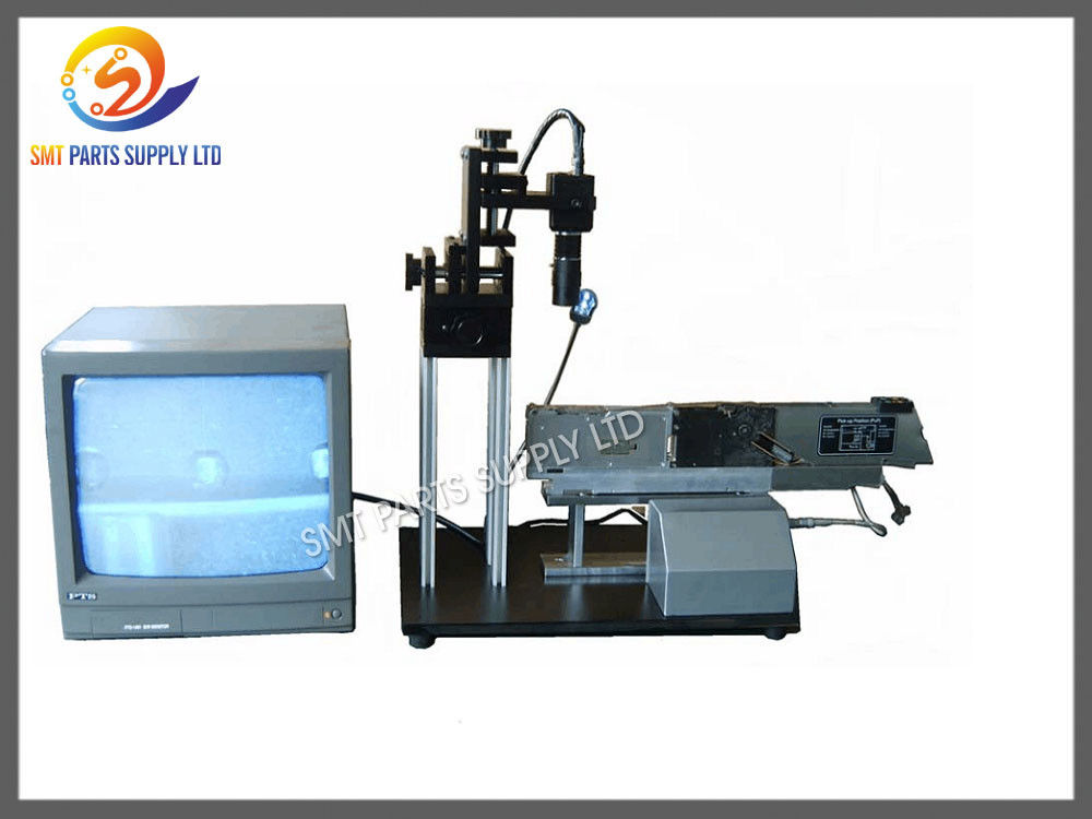
This product is used to confirm the location (adsorption position) of the belt feeder (Fei Da) and the special equipment for adjustment. This product uses CCD camera and high magnification, through the display case, observation of feeding up and down movement and lever thimble wear, reduce material frame caused by poor feeding problems, very good to improve the yield of the mount with help
* simple operation, simple and compact appearance.
* X, Y and H drive in three directions are precision screw drive. The guiding mechanism adopts two sets of precision linear bearings and precision guide pillars in each direction, which ensures the precision of transmission and guidance.
* CCD camera plus 50mm magnifier, with LED lighting to make the picture clearer.
* manually drive the FEEDER, simulate machine movements, and observe the dynamics of the gears.
* equipped with a standard correction ruler to adjust the suction center.
* Please install the monitor and connect to the 220V power supply. The CCD output terminal is connected to the video signal input interface of the monitor by the video signal line.
* connect the DC plug line to the power input jack of the CCD camera.
* connect the power supply of the electric control box to the 220V power supply.
* switch first open behind the electric control box, and then open the lamp, CCD and display the power switch, the display will show cross cursor; please check if the power supply and signal line is not correctly display. Adjust the brightness and contrast of the display to display clearly.
* mount the calibration ruler to a FEEDER with the best rate of mounting in the production, and place the FEEDER on the placing platform and secure it.
* press the forward button on the SIEMENS FEEDER to forward the feed gear several times, and observe the deviation of the cross cursor and the correction ruler in the display.
The focal length of the adjusting knob to display the correct focus and clear picture, then the X and Y direction adjusting knob to move the cursor in the display to cross the center position of the suction feeder standard, so the center is consistent with the cross cursor, the cursor to cross as a benchmark to determine the feeding interval position correction feeder.
(1) the correct feed interval shall be determined by standard feeder first,
(2) fit the correction ruler to the adjusted feeder. Note: please leave before the calibration ruler, from above70 about 30mm position determination.
(3) remove the end cover of the feeder that needs to be adjusted (as shown in Figure 1) and fit it onto the feeder base. (4) slightly loosen the worm gear retaining screws. (as shown in Figure two)
5) rotation of the motor shaft, will prevent to the card in the card on the device body axis, and finger to be suppressed, at this time, the motor shaft does not move, rotate the adjusting rod by the worm gear, worm gear drives a big gear of the feeding position is adjusted to the correct position, make the center position correction interval location hole ruler at the display of the cross cursor, then tighten the screw worm gear.
(6) loading and unloading 2 times, confirming that the interval has no change,
(7) press the forward button on the feeder several times to confirm that the feeding position is correct.
Contact Person: Mrs. kalinda wang
Tel: +86 18351183377
Fax: 86-0512-62562483